Laboratoire d’Étude
des Microstructures
et de Mécanique
des Matériaux
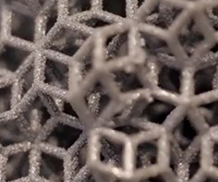
Le LEM3 est un laboratoire de recherche fondamentale et appliquée dans le domaine des Matériaux, la Mécanique et les Procédés.
C’est une unité Mixte de Recherche CNRS – Université de Lorraine – Arts et Métiers regroupant 250 personnes.
Nos travaux de recherche ont l’ambition de contribuer aux grands défis sociétaux en matière de santé, de transition énergétique et numérique.
ACTUALITÉS


PUBLICATIONS
AGENDA
25 Avr 2024
Séminaire
Julien Yvonnet : Méthodes de « clustering » pour l’accélération des simulations multi échelles non linéaires dépendants du trajet de chargement![]() Salle de réunion du 1e étage, LEM3 – site principal, 7 rue Félix Savart, 57070 Metz
Salle de réunion du 1e étage, LEM3 – site principal, 7 rue Félix Savart, 57070 Metz
10 Mai 2024
10 Mai 2024
Vie du laboratoire
Fermeture LEM3 (pont de l’Ascension 2024)![]() LEM3 – site principal, 7 rue Félix Savart, 57070 Metz
LEM3 – site principal, 7 rue Félix Savart, 57070 Metz
14 Mai 2024
Médiation scientifique
Pint of Science 2024 – IA et entropie au service de la mémoire des métaux !![]() La Douche Froide, 11 rue des Augustins, 57000 Metz
La Douche Froide, 11 rue des Augustins, 57000 Metz
le lem3 en chiffres

250
PERSONNES

70
DOCTORANTS

50
PROJETS DE RECHERCHE EN COURS

80
COLLABORATIONS
INTERNATIONALES

150
PUBLICATIONS
PAR AN

3
PLATEFORMES TECHNOLOGIQUES